Fully functional, Arduino‑controlled spring‑launch shuttle roller coaster
7.5 x 1.75 x 3.5 ft 40:1 Scale Compression Spring Launch Arduino Controlled Flywheel
Background
My first functional roller coaster prototype demonstrated that my design could complete a circuit, but it also exposed two critical shortcomings. First, I underestimated the train mass required for consistent circuit completion — a result of using the minimum calculated lift-hill height rather than building in a safety margin. Second, frictional losses along the track were higher than my calculations predicted. These lessons shaped where my designs needed to go next.
With the foundations I had set, I wanted to approach a new challenge, different from what I had taken on previously. Moving to a shuttle-launched coaster created an entirely new set of design challenges to handle. This model was designed to be as different from the first as possible while pushing the mechanical complexity significantly further.
Initial Design
As with my first model, the design process began in NoLimits. Building on the experience from that prototype, I developed a more detailed dynamic model to predict vehicle behavior more accurately. By combining experimental measurements taken from the physical v1 model with analytical calculations derived from my materials and geometry, I was able to establish direct friction coefficients for my specific wheel-rail interaction, producing simulations with significantly greater fidelity than those used in the first design.
The track layout was also shaped by a practical constraint that the model needed to be transportable. The width was kept within standard doorway clearance, and the baseboard was designed as two equal-length sections that could be separated and reassembled, allowing the full model to be moved without disassembly of the track or structure.
The track layout was also shaped by a practical constraint that the model needed to be transportable. The width was kept within standard doorway clearance, and the baseboard was designed as two equal-length sections that could be separated and reassembled, allowing the full model to be moved without disassembly of the track or structure.

NoLimits Side Profile

NoLimits Isometric View
Modeling
All ride & structure components were modeled in SolidWorks. The track and structure were split into 78 printed pieces.


Launch System
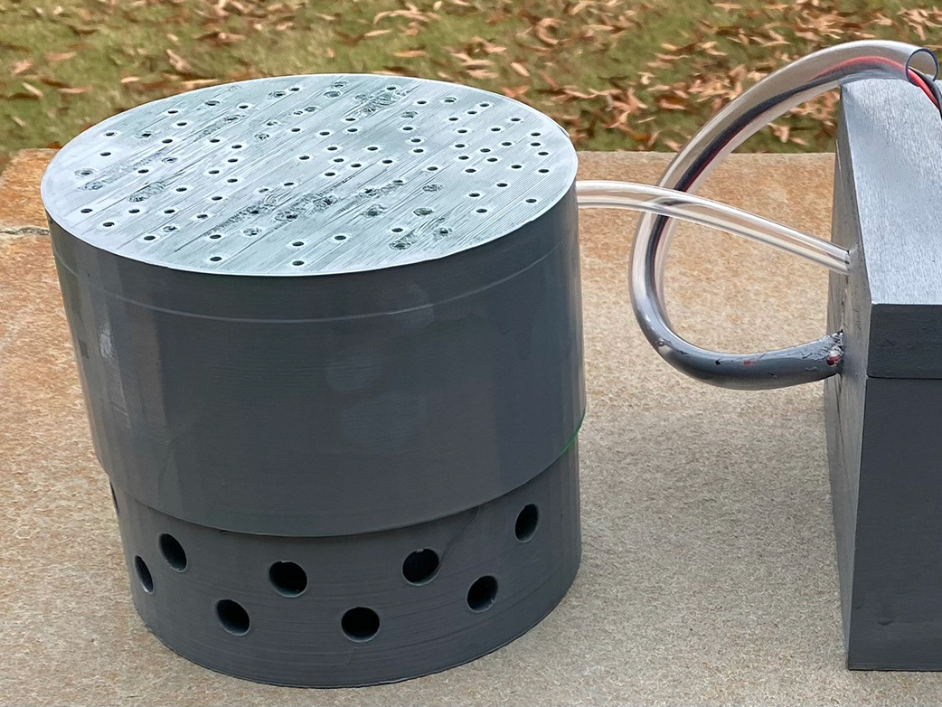
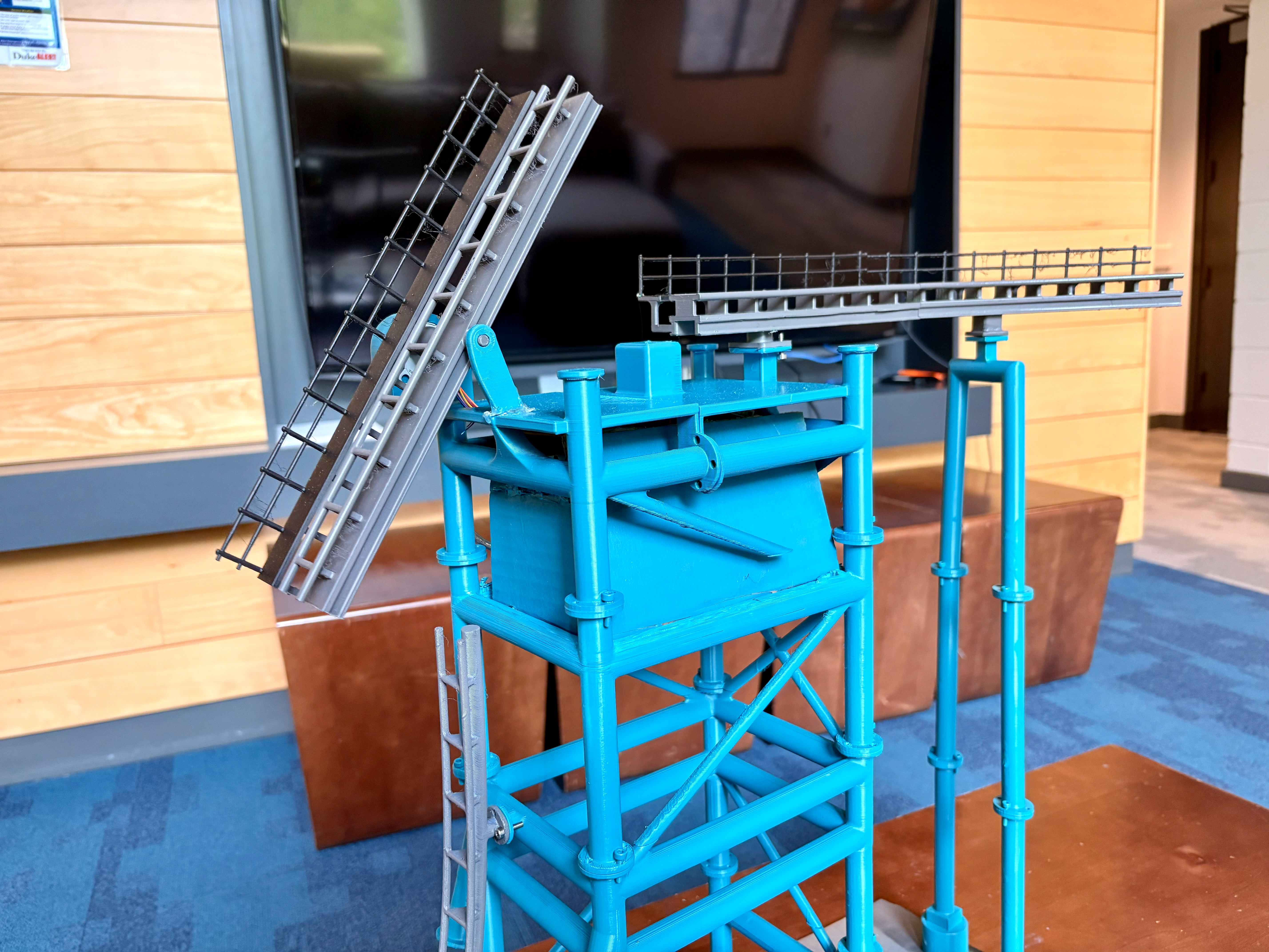
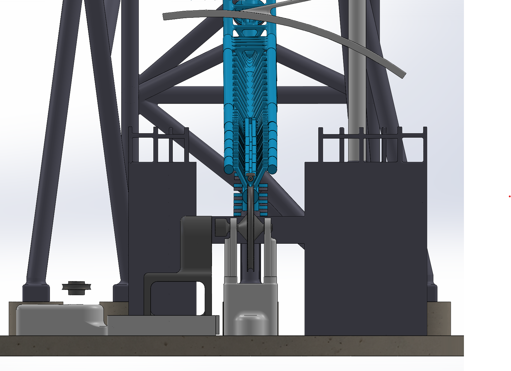
The launch system was controlled by an Arduino-driven flywheel mechanism. The launch section of the track was modeled with an integrated slot housing a compression spring. In the initial design, the front end of the spring was attached to a slider within the slot. The slider interfaced with the rear of the train on one side, while a string ran from the other side through the spring and around the flywheel. The first motor rotated the flywheel counterclockwise to wind the string, progressively compressing the spring. When the coaster was ready to launch, a second motor using a rack-and-pinion mechanism retracted the first motor away from the flywheel, releasing the string and allowing the spring to decompress and accelerate the train forward.
Two issues emerged during initial testing. The first was spring misalignment: because the track-to-track connections used rigid walls, slight design imperfections caused the edges of the spring to catch on the joints between track pieces. This was resolved by reprinting the edges of the launch slot on each track piece with a small fillet radius, eliminating the catch points.
The second issue was inconsistent coupling to the train. The original slider lacked sufficient grip on the ride vehicle to deliver a reliable, repeatable acceleration force. To address this, the slider was replaced with a dedicated catch car. The catch car featured a circular profile running through the launch slot, securing it to the spring and ensuring consistent, front-facing contact with the ride vehicle throughout the launch stroke.
Catch-Car Launch System Test
Train Improvements
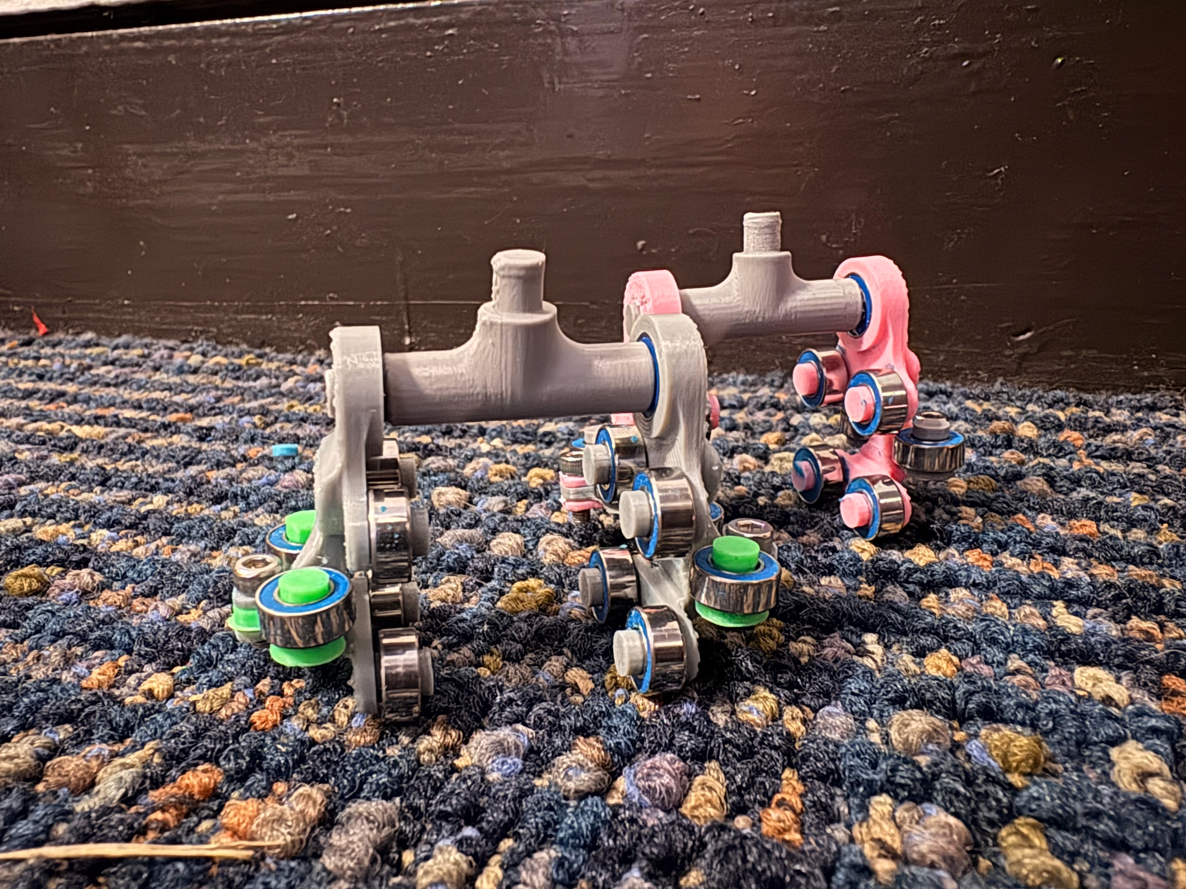
The most significant limitation of the previous train design was excessive friction and an insufficient number of rotation points. To address this, the trains used in this model incorporated a sub-chassis rod connecting the bogies to one another and to the main chassis through a single central pivot point, allowing for smoother rotation and more compliant tracking through changes in track geometry
Revise Chassis Connector

Train Final Prototype

Train Assembly Front View

Train Assembly Side View
Assembly
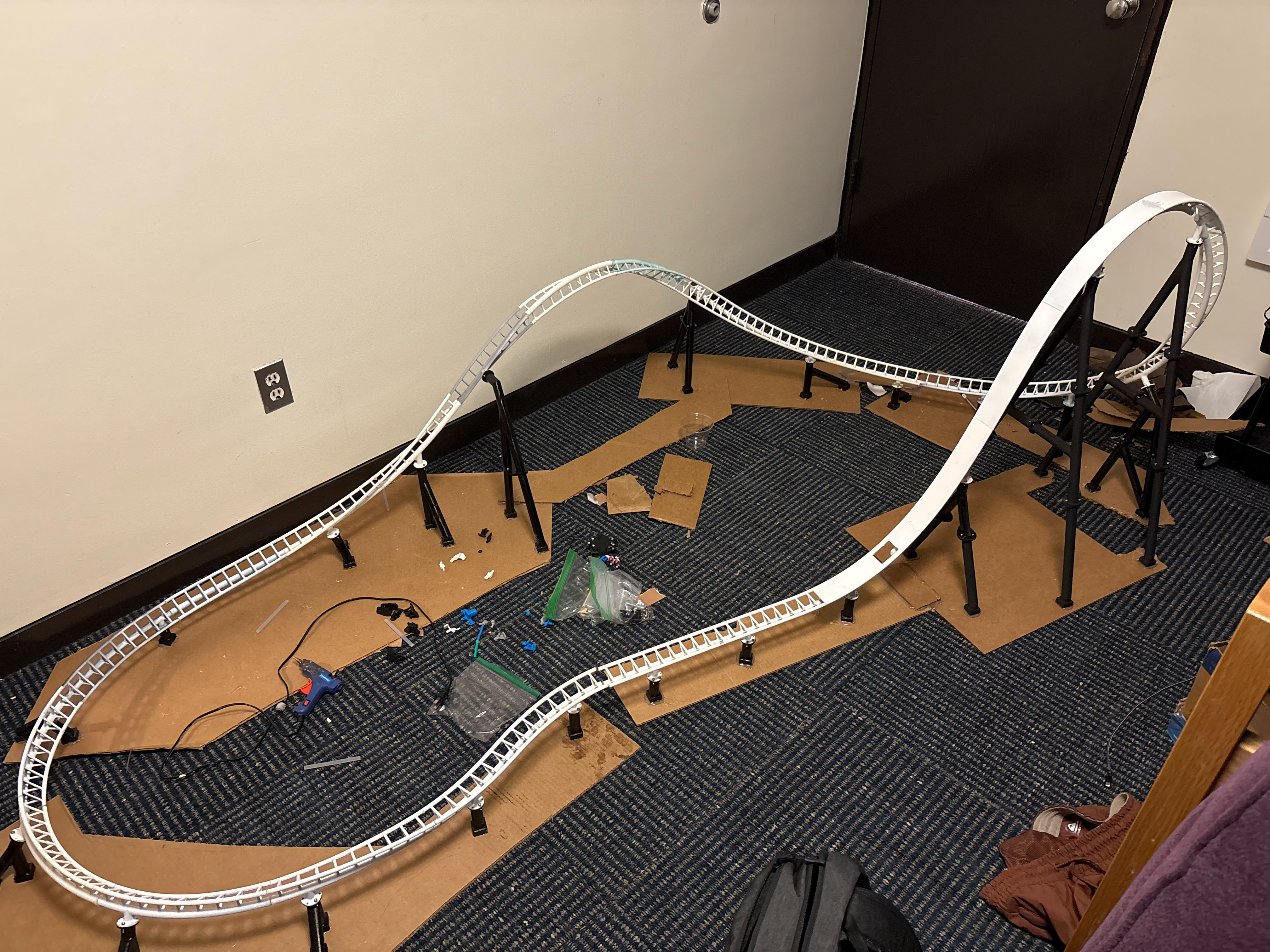
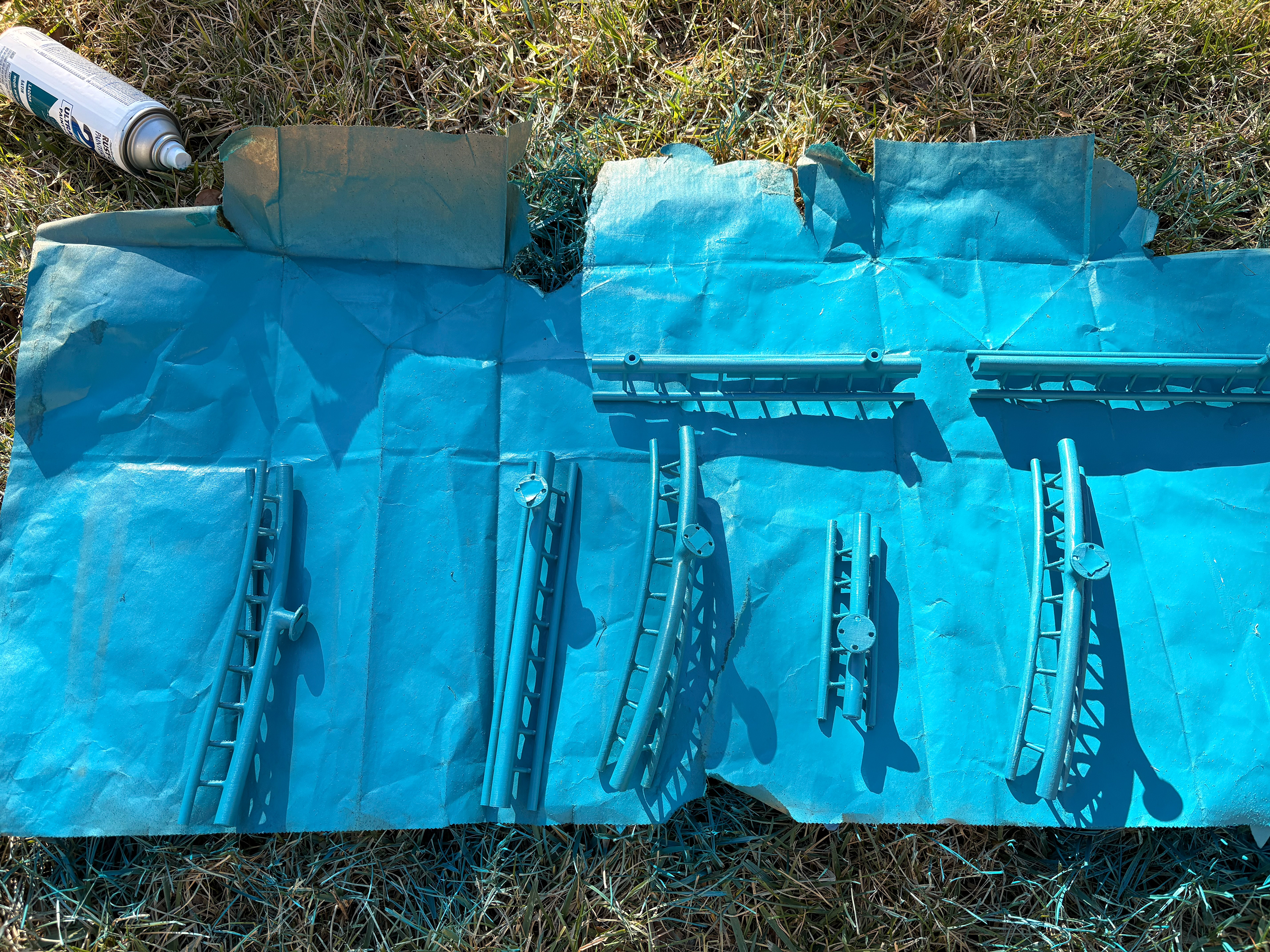
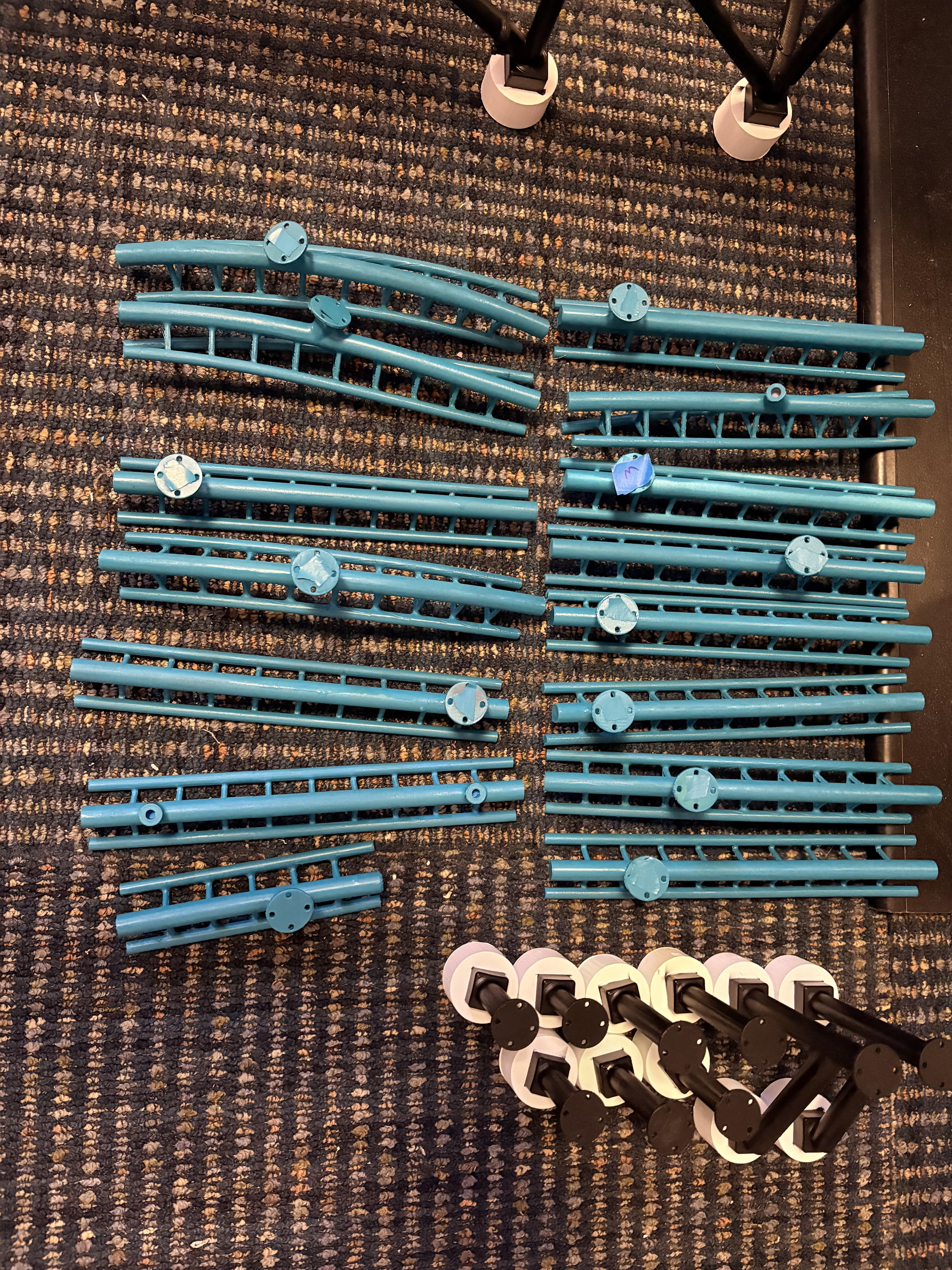
Each component was printed, sanded, and painted. The images below show different stages of the assembly process.

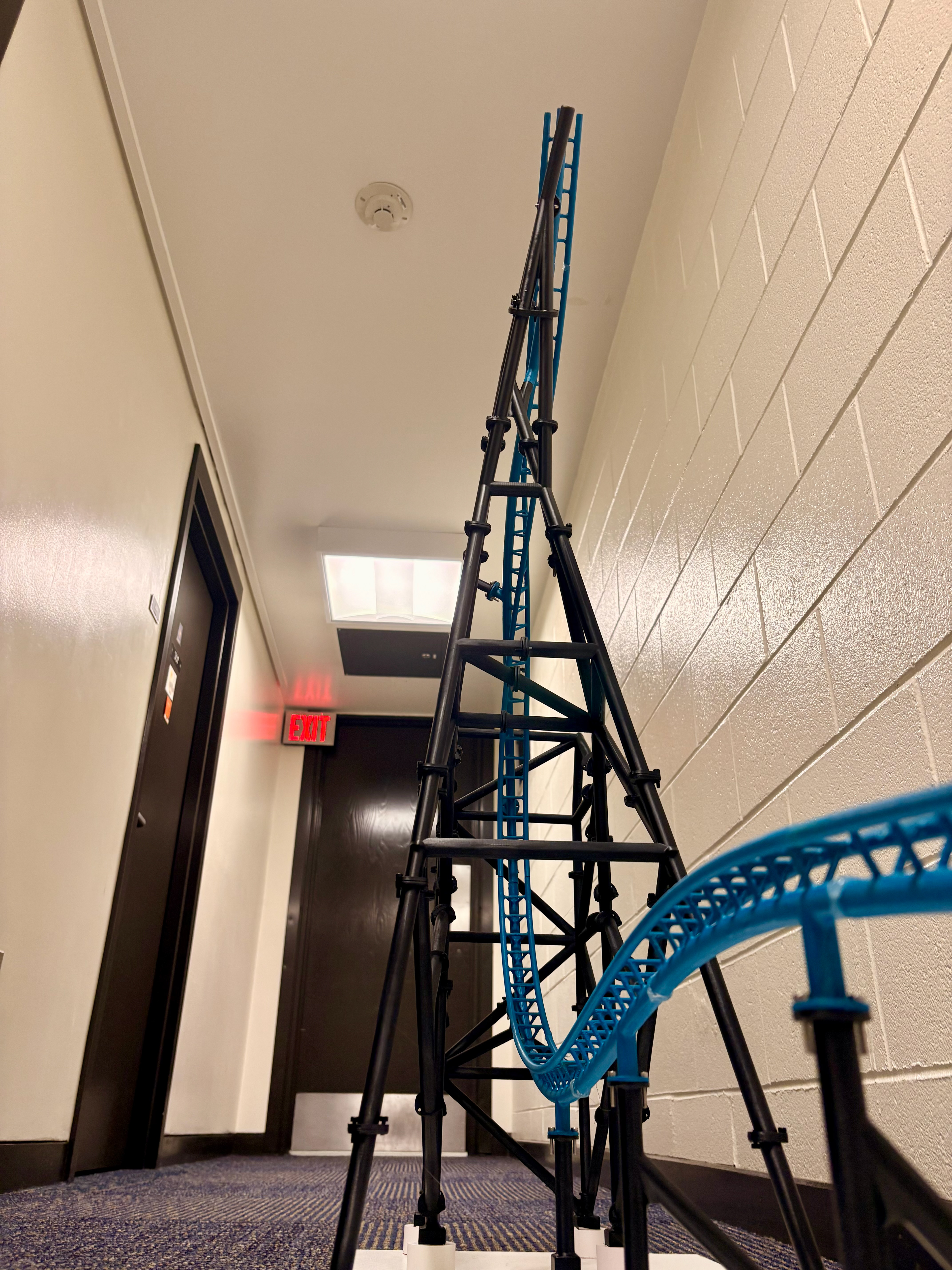
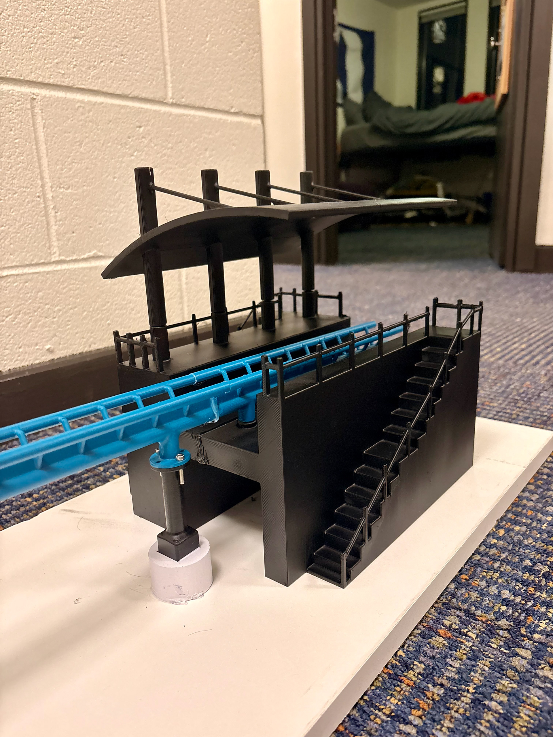
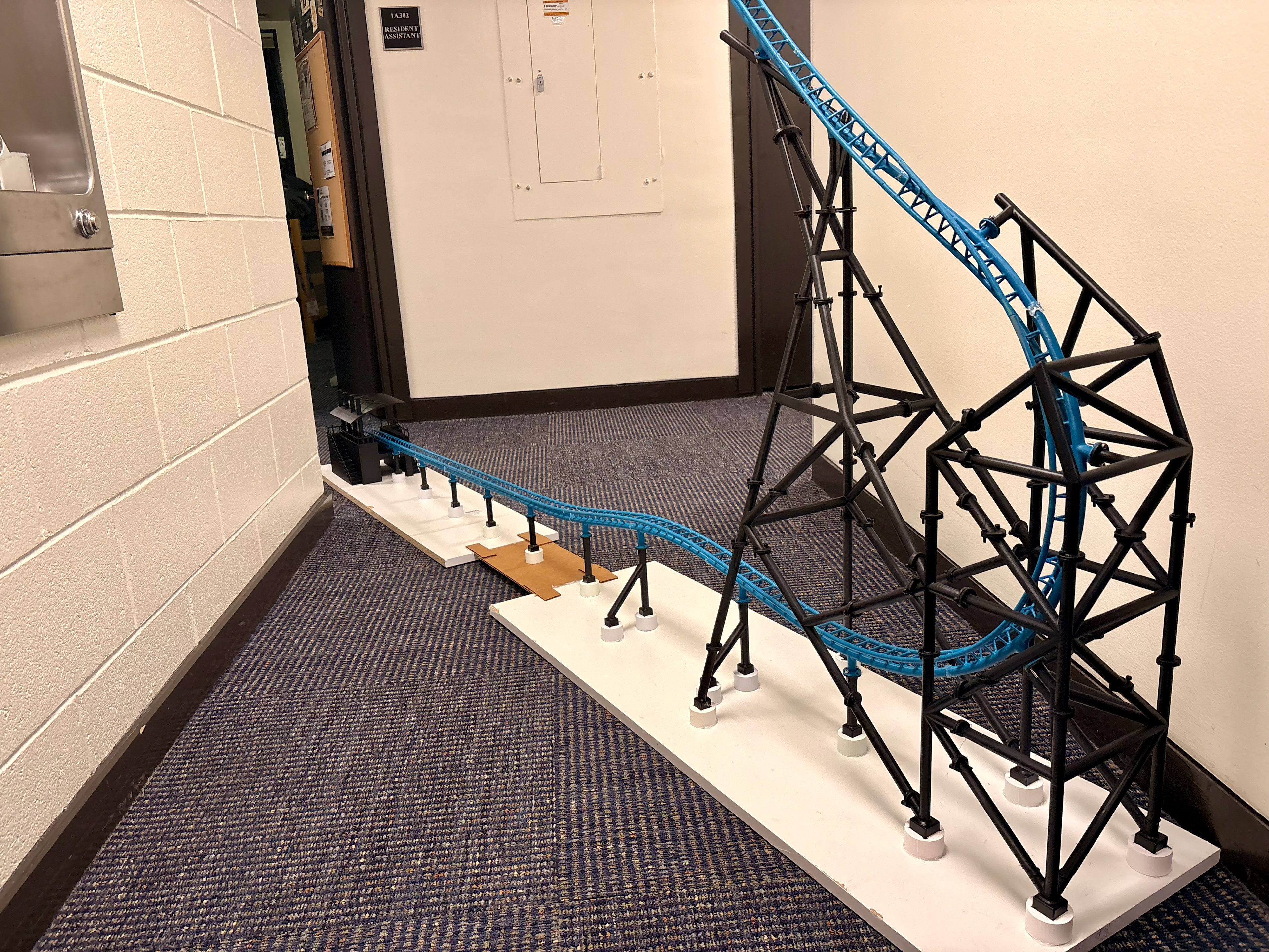
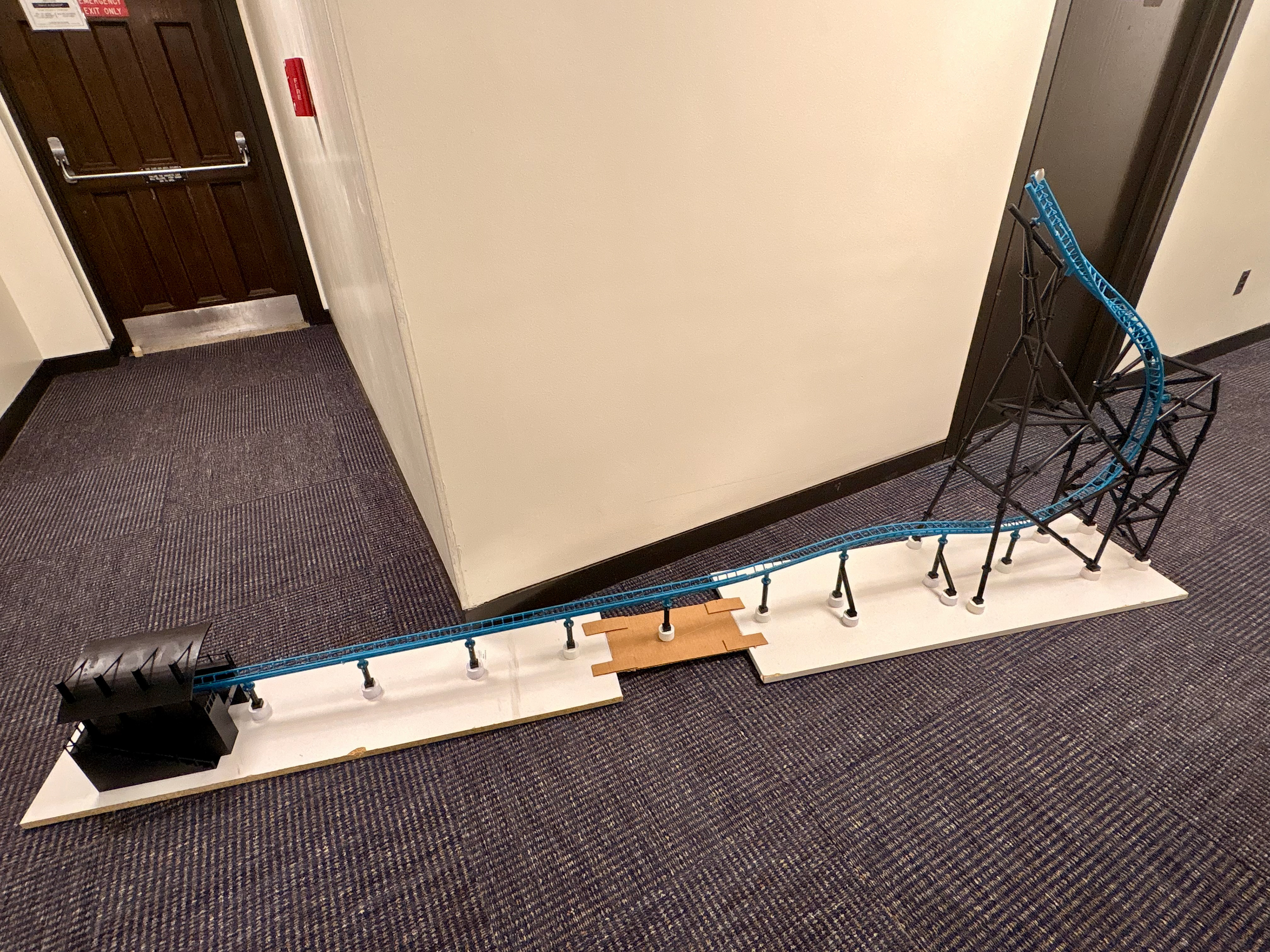
Final Model
The initial assembly images above show a small connection between the two white baseboards. Early testing and launch prototyping revealed that the launch section included unnecessary extra length, so the first segment was removed. Minor modifications were then made to the new first track segment to properly integrate with the station and launch system. A video of the final model is shown below.
Future Steps
This model was the second of two primary prototypes I developed to identify key design constraints and refine modeling methods for a more complex ride system. The insights gained from both the design and operation of these functional models will be applied to a larger project I am currently working on. Since completing this model, I have also built two static models to further explore and prototype specific design ideologies and constraints.