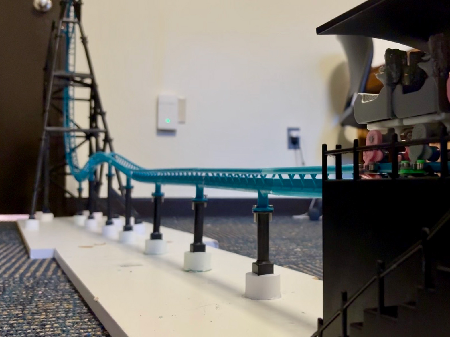
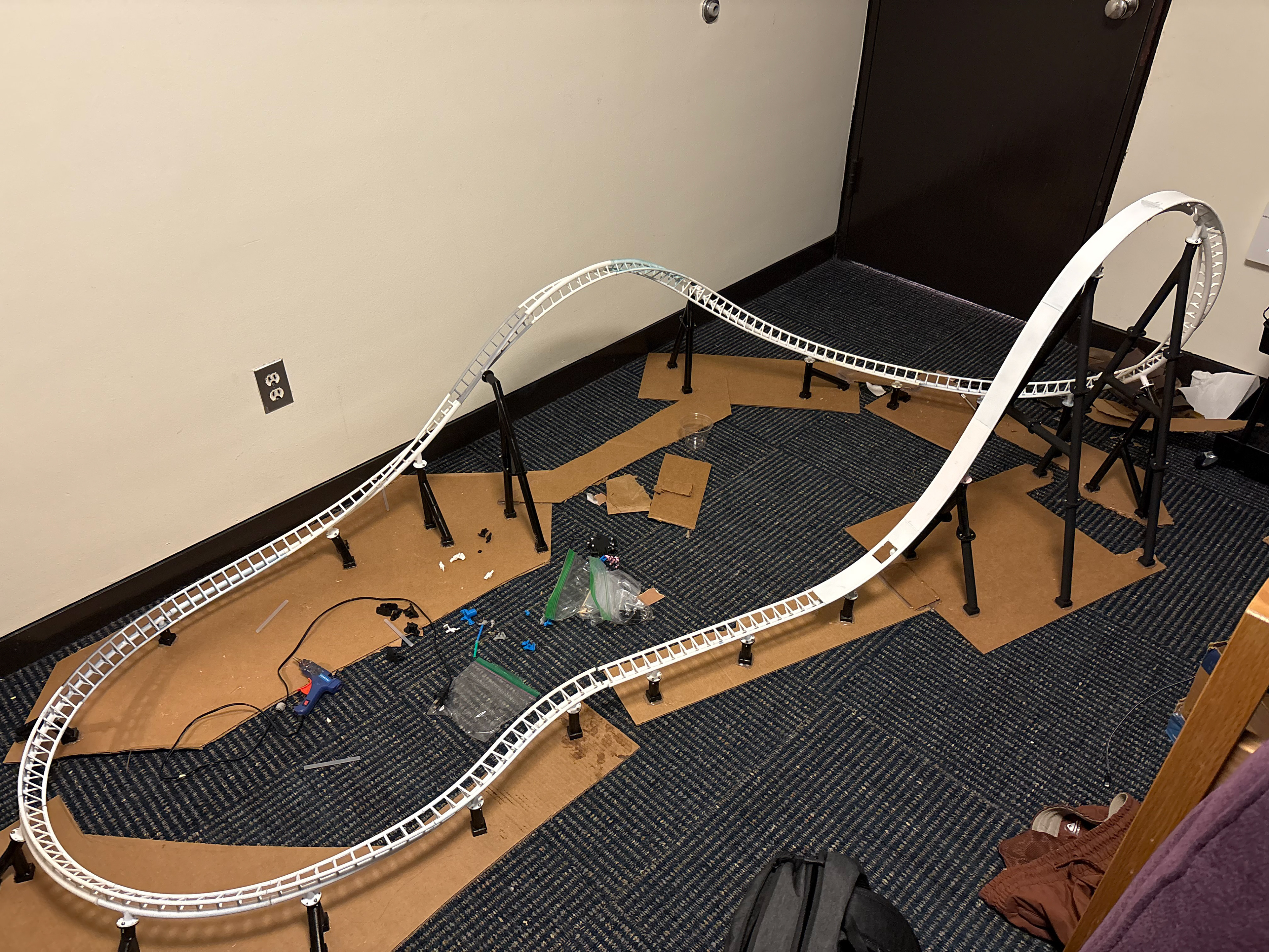
Montage of my 1st version functional model
The Beginning
The project began with a central question: how could I connect my passion for roller‑coaster design with my studies in mechanical engineering and materials science?
I started by developing a method to convert my coaster designs from NoLimits Roller Coaster Simulation into 3D‑printable models.
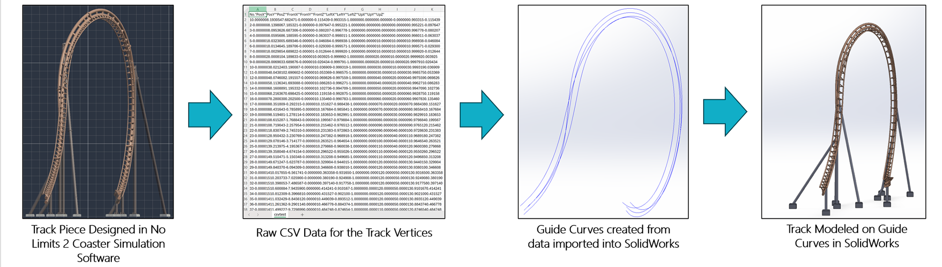
Transition Process of No Limits track to SolidWorks Model
After researching existing workflows, I discovered that NoLimits Coaster Simulation allows CSV spine data to be exported and then converted into TXT rail files that can be imported into SolidWorks as curve geometry for track modeling.
To streamline this process for creating a physical model, I wrote a Python program that generates the three primary rails based on custom inputs for rail and spine gauge. Because a large‑scale model cannot be printed as one piece, the program also accepts a user‑defined arc length and automatically divides the track curves into the appropriate number of segments. It then creates a directory containing a numbered folder for each segment, each with its own TXT files for the right rail, left rail, and spine rail. This workflow enables rapid modeling of individual segments and ultimately supports the creation of manufacturable components.
This function exports only the rail curves, not the supports or full track geometry.
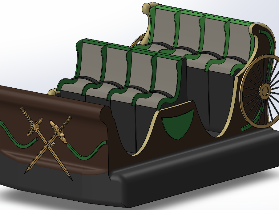
Static Prototype
After developing the program to transfer my coaster’s rail geometry into SolidWorks for full 3D modeling, I began designing my first static model to identify design challenges and constraints that would inform a future functional version.
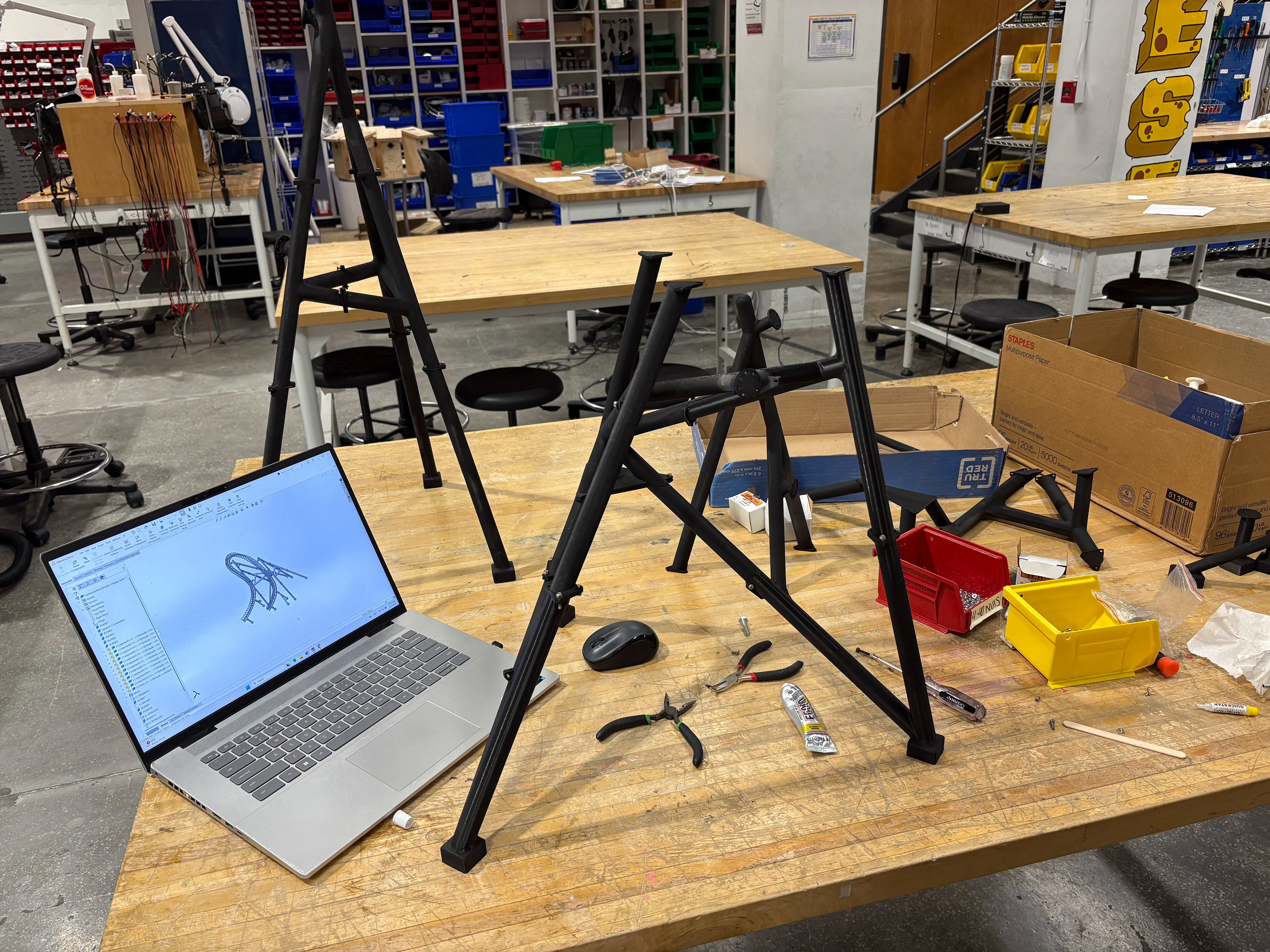
Top Hat Support Construction
Static Train Assembly
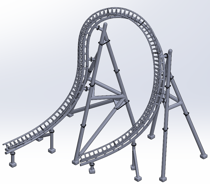
Full SolidWorks Assembly
This static model established the baseline design for my track geometry, train configuration, and support structure. It also informed key decisions regarding scale, manufacturing approach, and assembly methodology, including both track-to-track interfaces and support connections. The final prototype measured approximately 4 × 4 × 4 feet and incorporated more than 100 custom-designed components.
With the static model complete, I shifted focus to my first functional design. This stage was intended to develop the engineering and design principles that would later support a more complex, fully functional model, such as my current project.
Functional Model Design
The static prototype established my principles for track and support scale, which made the SolidWorks construction of my model straightforward, but still time-consuming.
Initial Design
By conducting background research and physical testing, I calculated a custom friction coefficient and applied it within NoLimits 2. To further verify the feasibility of a complete circuit, I used the friction‑testing results to perform energy calculations that established the required relationship between maximum lift height and overall track length.
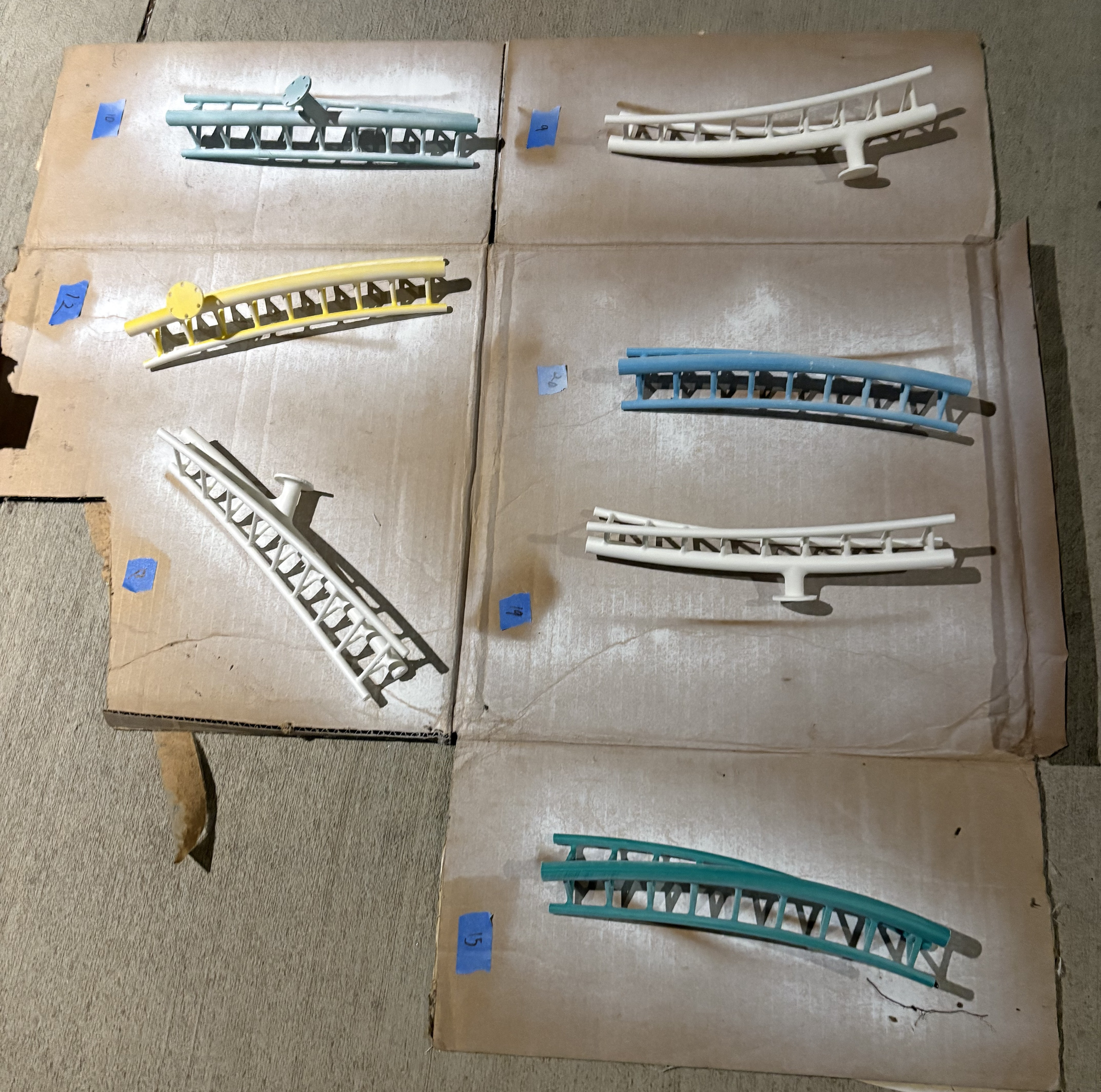
After finalizing a feasible design in NoLimits, I used my Python script to convert the rails into 27 track segments, then modeled the track and support components in SolidWorks for assembly. The overall approximate track scale is 35:1.
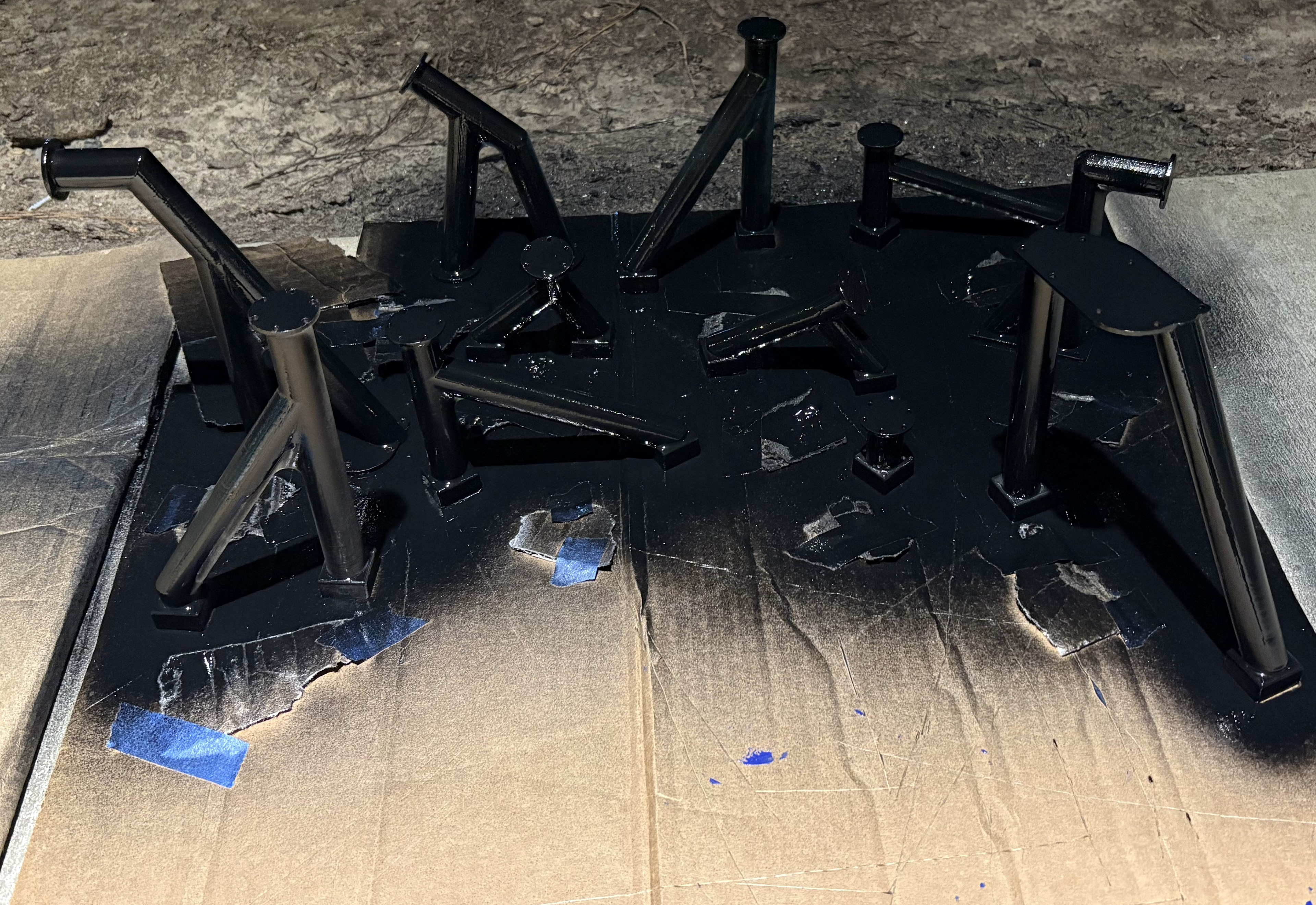
The support structure was developed by blending typical roller‑coaster support geometries with calculated force requirements. I analyzed the estimated loads at key points along the track and used those results to determine column placement, bracing angles, and connection locations.
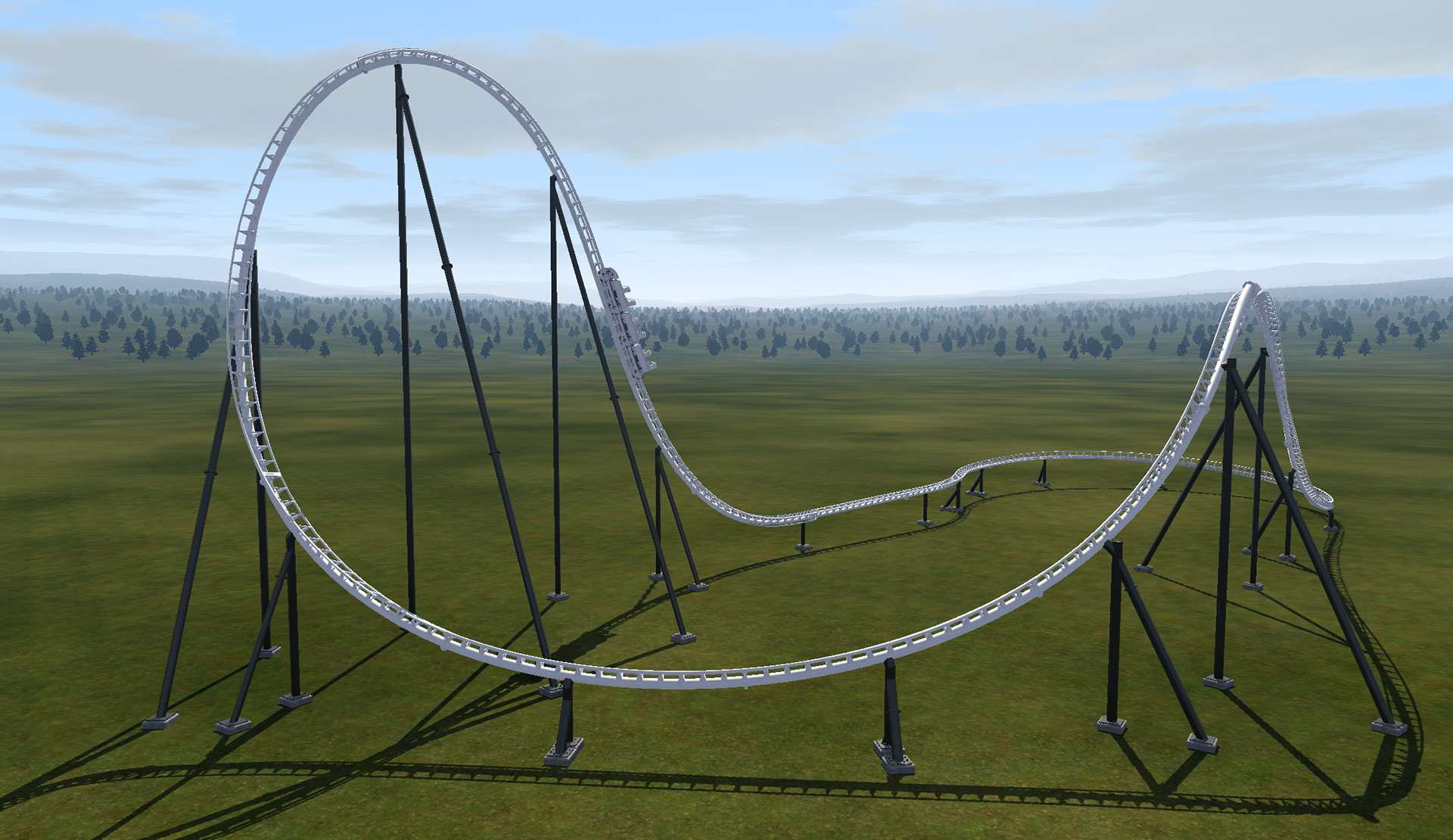
No Limits Coaster Simulation Design
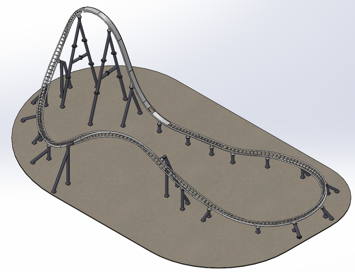
SolidWorks Assembly of Layout
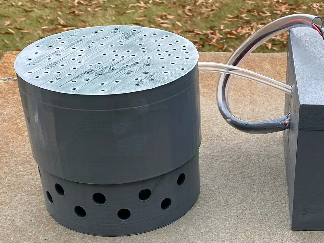
Train Development
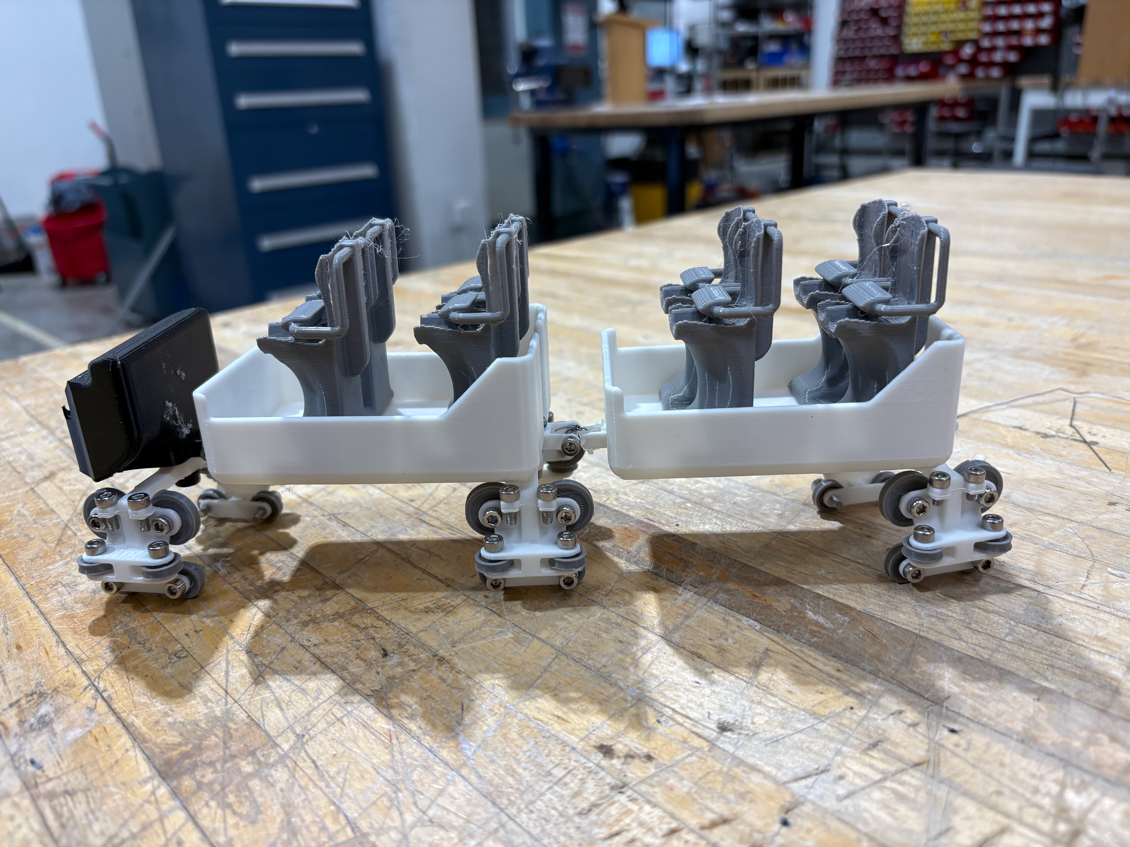
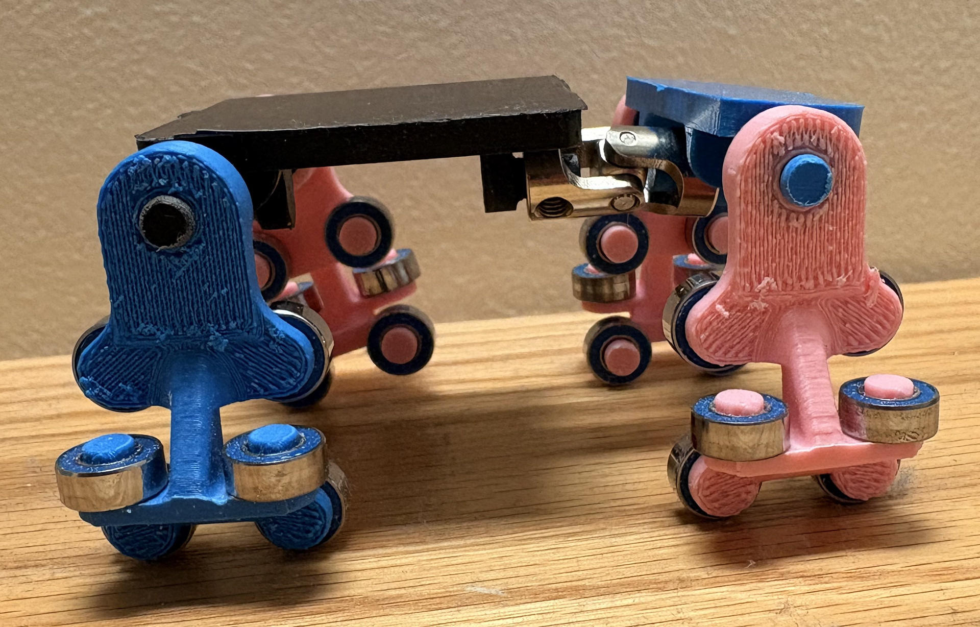
1st and 2nd Version Train Prototypes
My initial chassis and bogie designs struggled with two key factors: mobility and stability. The print‑in‑place ball joints provided excellent mobility but resulted in poor stability; when the joints were constrained, stability improved significantly. In addition, each bogie used only a single wheel set on each side, which contributed heavily to the instability.
1st Version Wheel Bogie
2nd Version Wheel Bogie
Ball Joint Chassis Connection with 1st Version Wheel Bogie
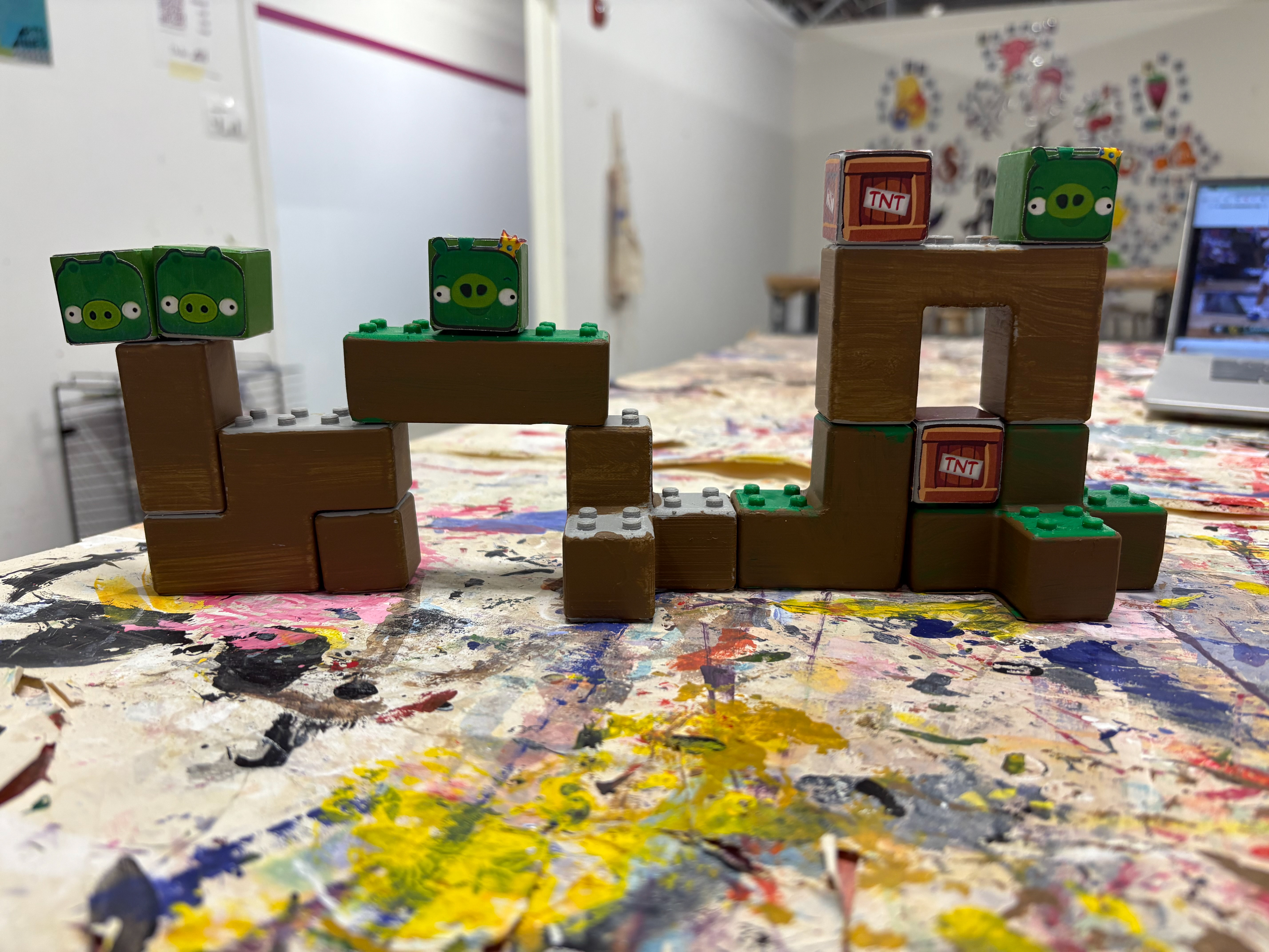
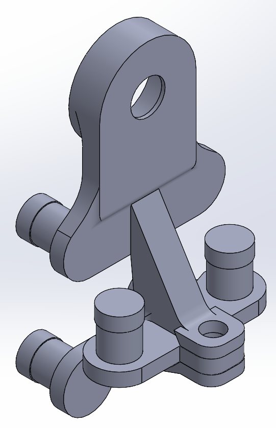
3rd and 4th Version Prototypes
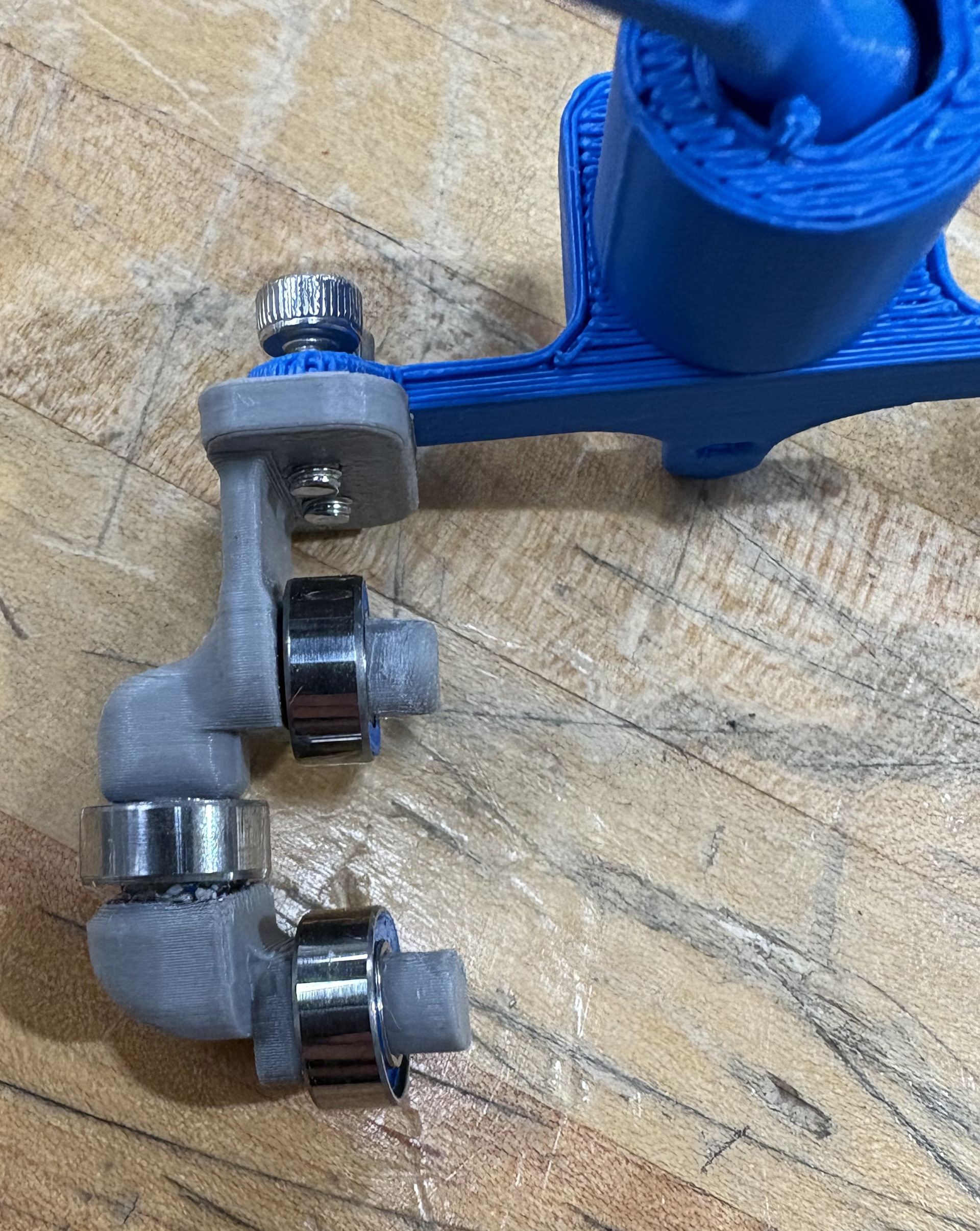
The next bogie prototypes addressed both issues. The chassis incorporated purchased U‑joints and two wheel sets per bogie, significantly improving stability and mobility. I also introduced a ball‑bearing interface between the chassis and bogie, adding a degree of freedom.
The bearings were attached using a snap‑fit feature: a 2 mm‑wide ring slightly larger than the bearing’s inner diameter allowed the bearing to snap into place under light pressure. This provided free rotation while maintaining proper alignment.
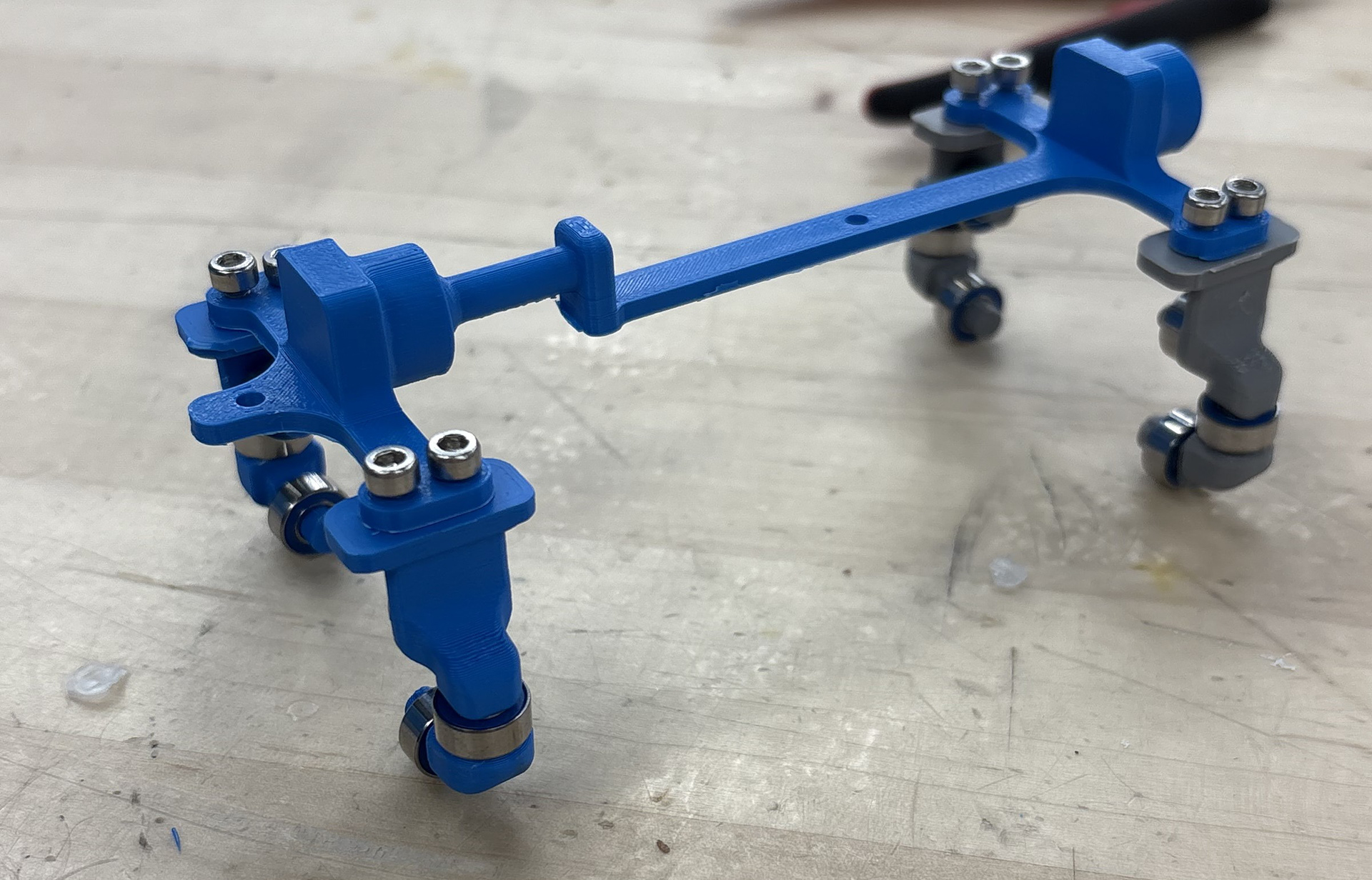
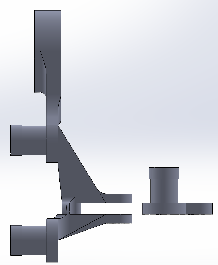
3rd Version Train Prototype
The primary issue with the third‑version wheel bogie was friction. After assembling the train, the design failed greatly: the guide wheels on the bogies weren’t rotating as intended but instead were sliding along the track, generating significant frictional forces. The train merely slid along the tracks.
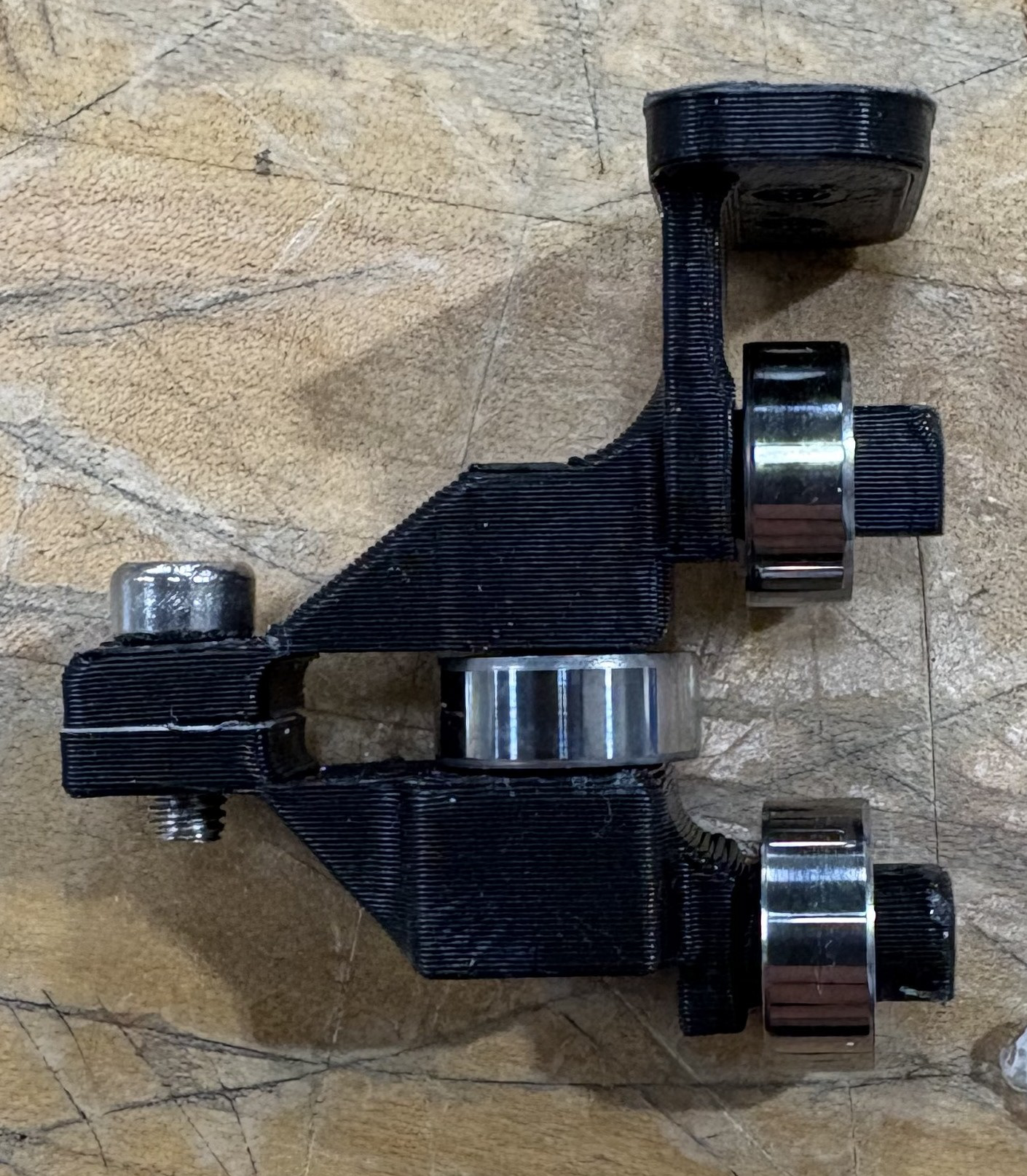
To resolve this issue, the fourth‑version wheel bogies were redesigned by splitting the third‑version bogie into two separate parts. This allowed all of the ball‑bearing holders to be printed vertically, which significantly improved print accuracy and eliminated the alignment problems present in the previous design.
This small design change led to significant improvements in train performance, especially after adding a small amount of weight.
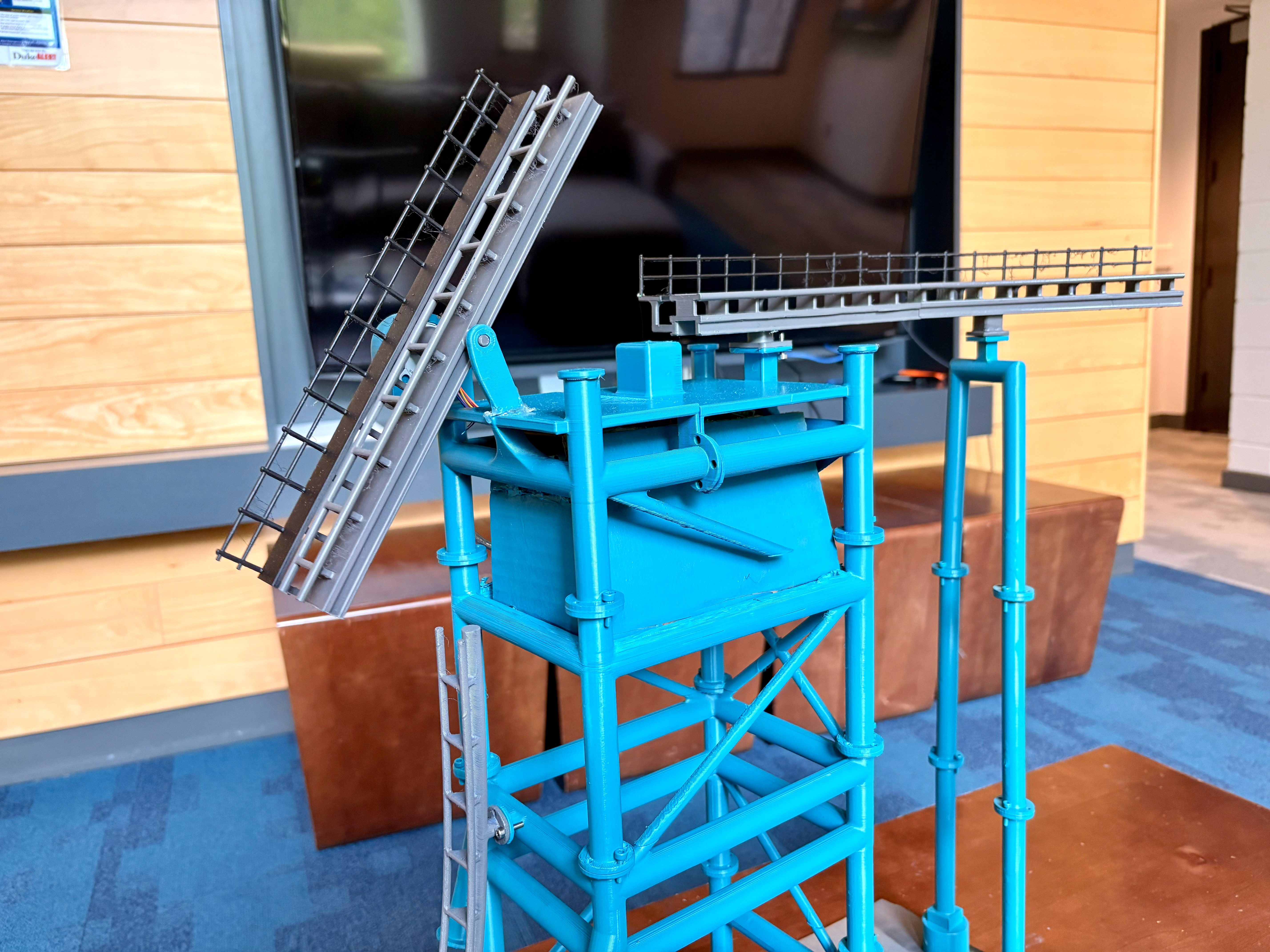
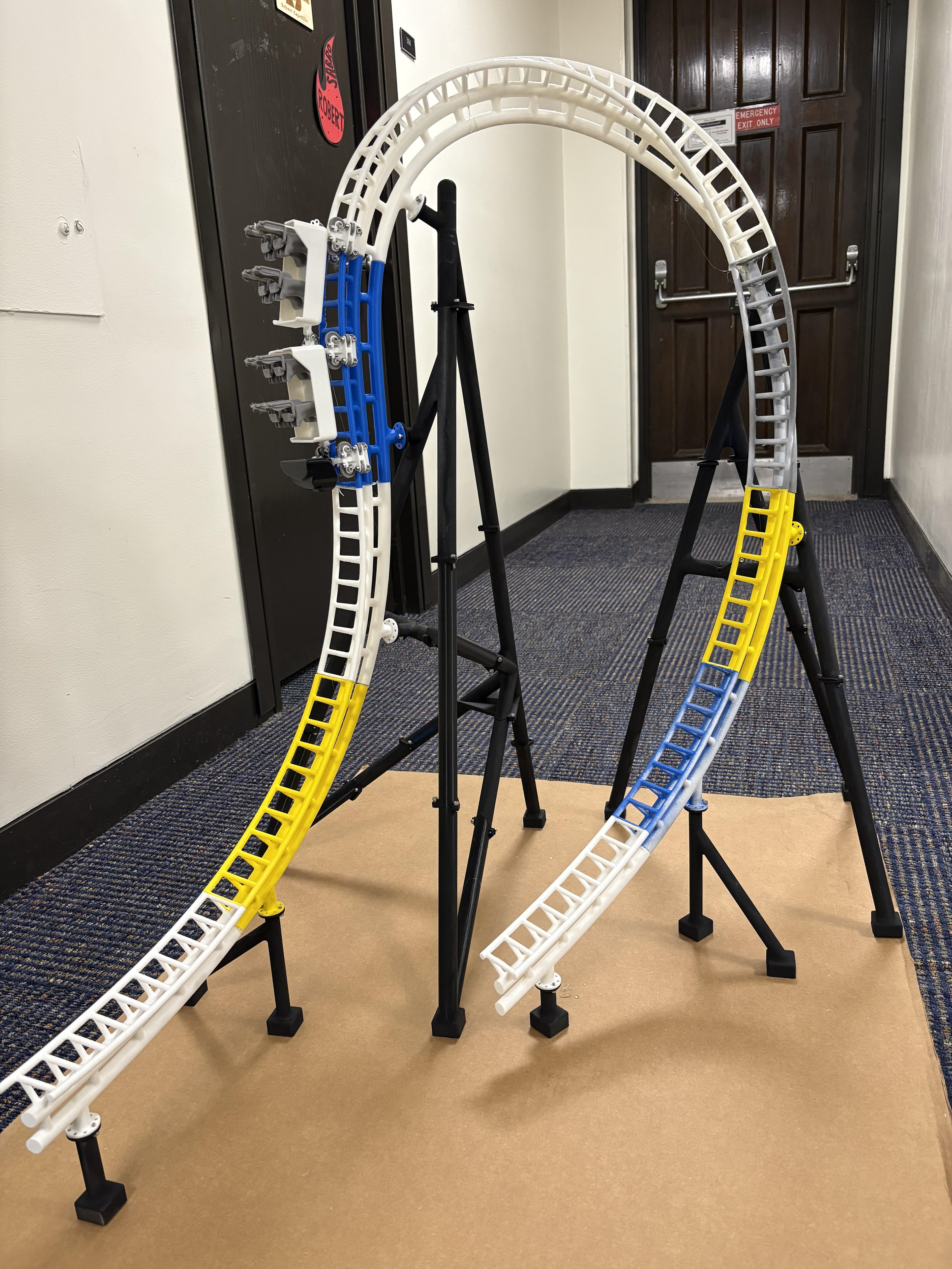
Physical Assembly
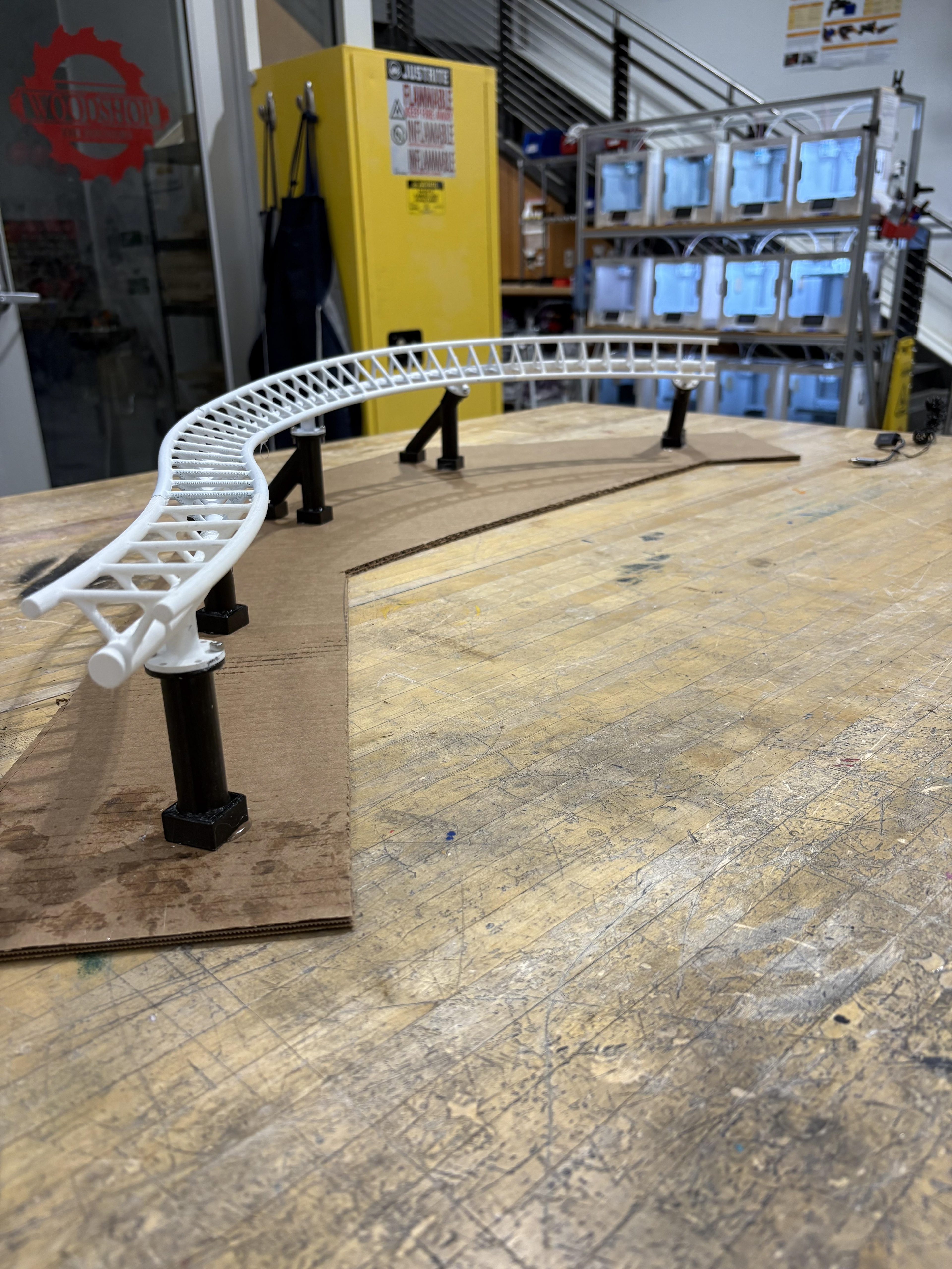
Physical assembly began with sanding all printed track and support components. The model was built over the course of a month in three major sections to allow for easy transportation between the lab and storage.
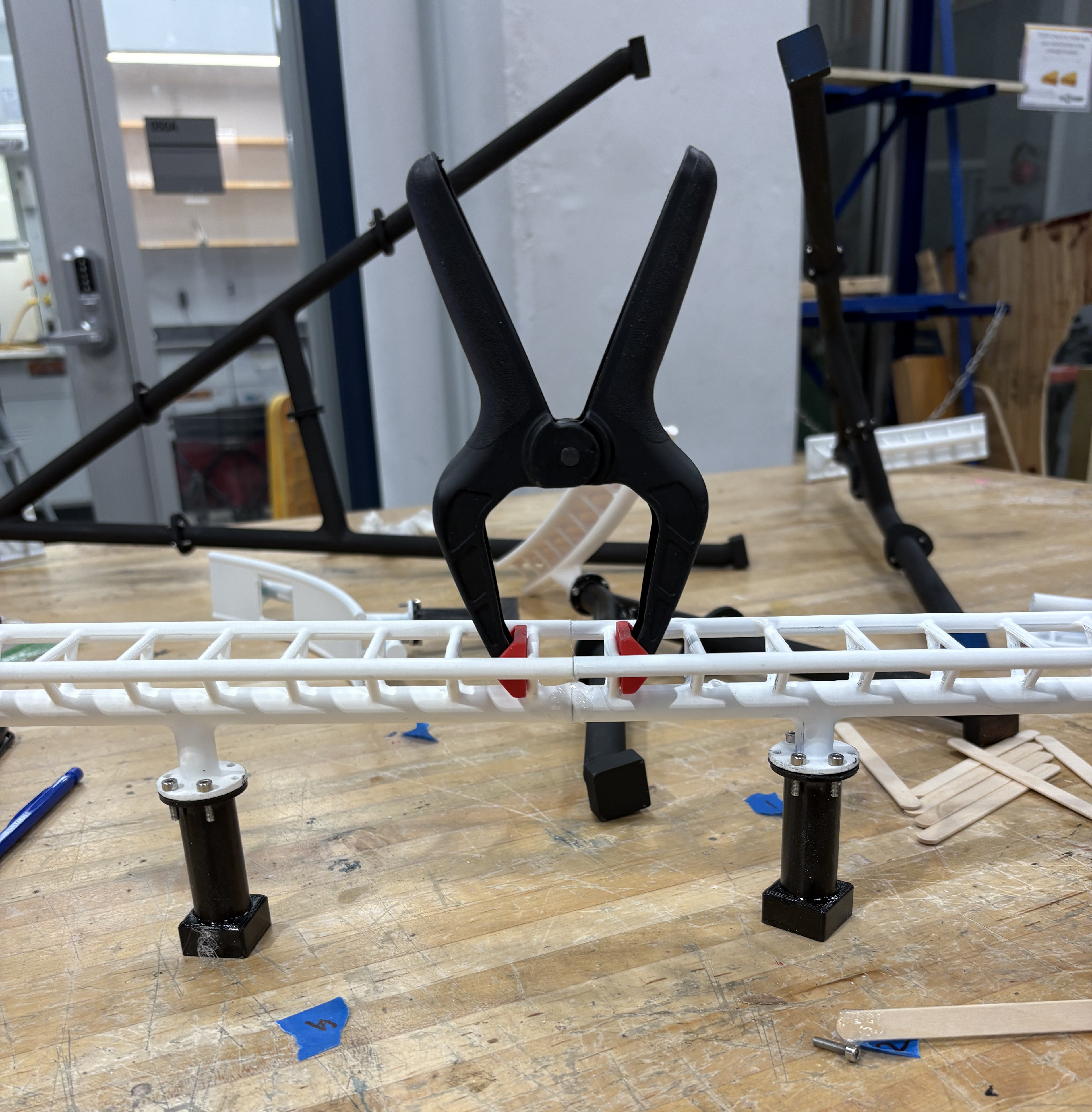
Working in segments also helped refine my assembly methods. By the second and third sections, track‑to‑track connections were noticeably stronger and more accurately aligned, largely due to the addition of clamps to hold pieces in place while the hot‑glue joints cured. Small amounts of hot glue were applied at each rail joint, followed by extensive sanding at the connection points to minimize alignment errors. All track‑to‑support connections were secured using threaded screws.
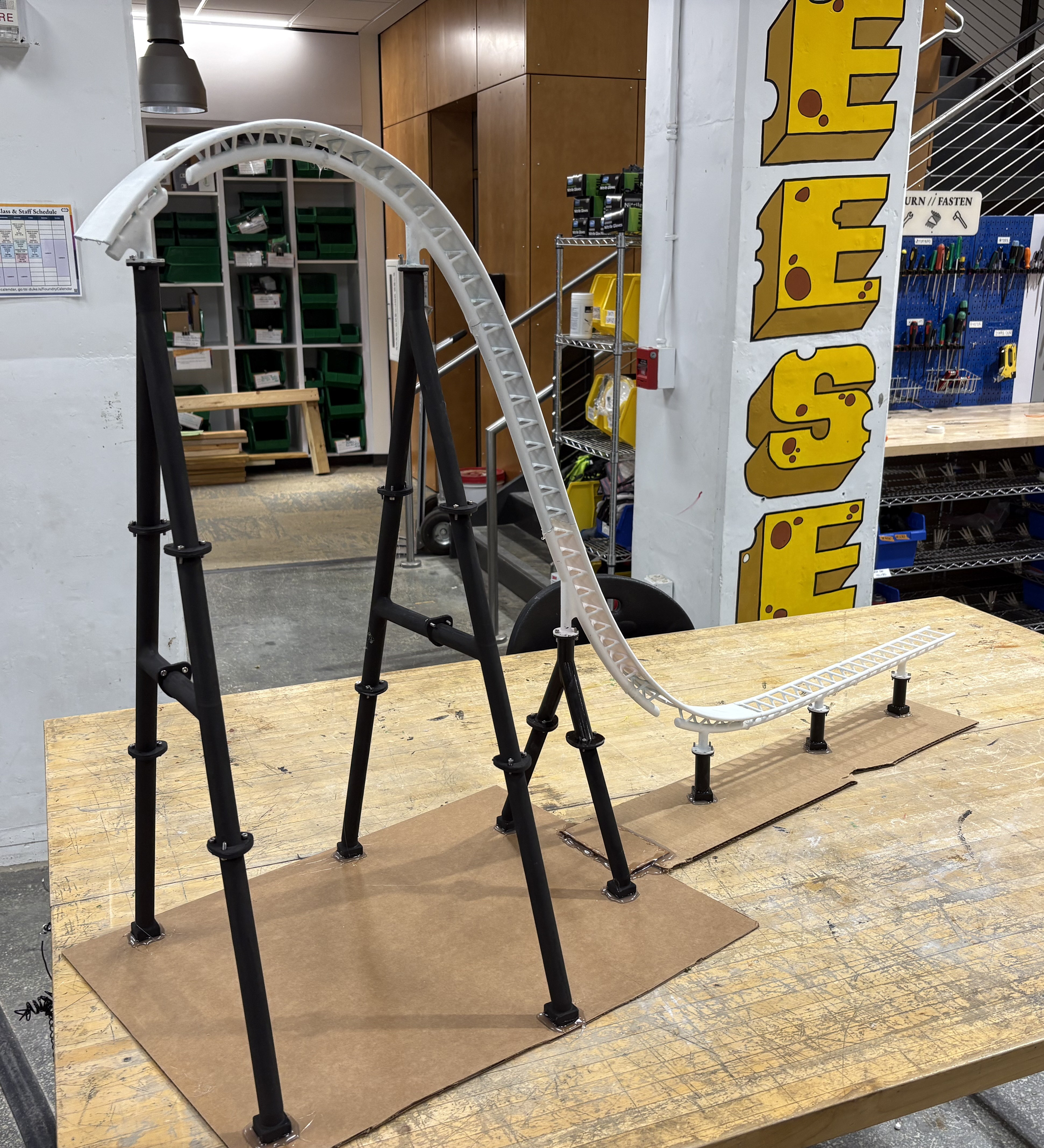
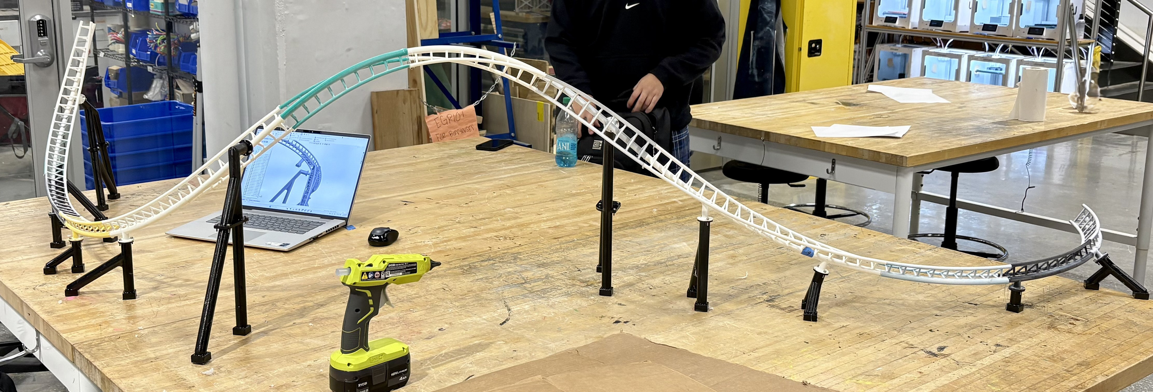
Final Prototype
Reflection
This prototype served as an essential bridge between initial concept development and a fully functional design. Working through the challenges of this project pushed me to strengthen my problem‑solving and critical‑thinking abilities. I gained substantial experience in designing for manufacturability, iterative prototyping, and the fundamentals of structural engineering.
The model serves as a strong foundation as I move towards more complex, functional designs such as my current project.